High Pressure Fan Prototype
Older fan has proven insufficient for task.
Goals:
- No/little weld solution
- High Static Pressure
- Lower CFM but maintain high static "/h20
- Withstand High Gas Temperatures
- Low cost
Reasearch Notes:
Modeling the fan after various concepts from Cincinnati Blower.
Version 1:
 Modeled in SolidWorks 2010. CNC Plasma Cut.
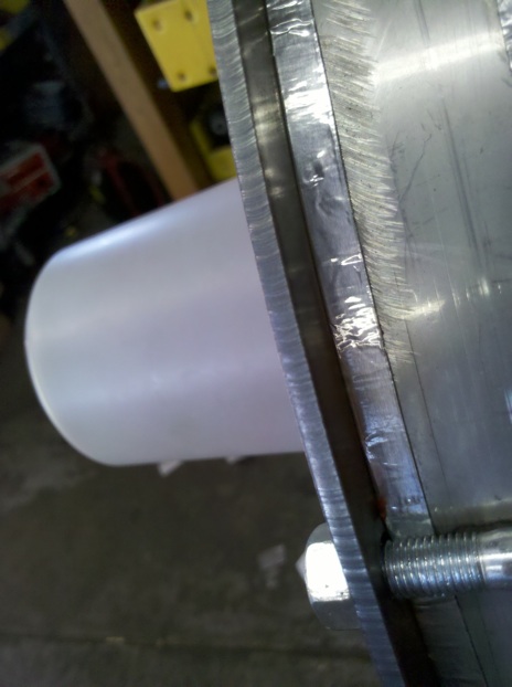
 After a serious round of figuring out the simplest means by which to seal the fan. I pretty much threw out most of the rubber/silcone gaskets as impractical. Also due to thier close to failure temperature ranges, and installation pain. So I Decieded to try FOIL aluminum tape. Bingo. Worked great. In fact this worked so well, we are going to pursue more options within that idea. Copper Beryllium tape would be ideal as the coefficient of expansion is roughly the same as steel. But I'd be happy with close enough.
We ran two tests of this, both with our 12vdc Fan motor (cheap/low cost) and the same cowling and test set up. The only difference was the rotor size. We maintained the blade to rotor ratio DIA, and kept the blade at the same width. 0.7"


Our first test we ran with a rotor of 10"DIA. The Second with a rotor of 11.5"DIA. Note the ID of the blades stayed the same on both rotors. Close to the hub as pictured. The OD followed the rotor diameter.
Here are the results. (in brief) Again note that this a 12VDC fan-motor, the rpm drops under load. And note that the decreasing rpm in each test refer to a different motor speed wire.
Fan Results:
Static test, 4" intake blocked at 5" depth.
10" rotor 12" cowling 0.7inch blade
Battery @13v with addition of charger. (to maintain charge and current)
4200rpm = 8.75inches/h2o orange wire -high power
3150rpm = 5 " red wire -med power
2200rpm = 2.75 " yellow - low power
11.5" rotor with same cowling set up and batt/charge.
3500rpm = 8.3 "
2641rpm = 4.7 "
1796rpm = 2.3 "
- So what we are seeing is a dramatic improvement of "/h20, (last fan 4"/h20) the second test is lower due to the drop in RPM due to the larger rotor's greater 'Blade' Bite. Here it is suggested that if we lower the bite of the 11.5" blade and we should begin to 'see' an increase of "/h20 as the tip speed again increases... but we'll hold off till the next round for proof.
- Which suggests again that being a centrifugal fan that as we increase tip speed, we increase "/h2o.
- It was also determined that the fan still maintained adequate CFM across the board and possibly still to much which again allows for more room to increase "/H20.
- One definite pleasurable result has been... lower fan noise. (probably due to the improved mount, efficiency, and rotor balance.)
The next design we should be able to achieve the 10"/H20 mark that we have set out to do.


Comments (0)
You don't have permission to comment on this page.