Rev: 4.3; Date: 041112
return to How to Build and Run the GEK Gasifier
GEK TOTTI Assembly Instructions
Pyrocoil and Auger/Drying Bucket Add-ons
v3.x & v4.x


The GEK TOTTI includes the Basic GEK with the TOTTI Add-on components; the Auger/Drying Bucket and the Pyrocoil. First, assemble the Basic GEK according to the instructions here: http://wiki.gekgasifier.com/w/page/27905807/Assembly%20Instructions%20for%20the%20GEK%20v4%20Kit
|
Why the GEK TOTTI? The GEK Tower of Total Thermal Integration (TOTTI) incorporates the Pyrocoil and the Drying Bucket as heat exchangers to increase the efficiency of the gasification reaction by integrating needed heating and cooling steps in the system. The Drying Bucket heats the incoming biomass while cooling the hot producer gas exiting the Reactor. The producer gas must be cooled so that any condensates will separate from the gas stream thus promoting a cleaner gas stream. The vertically off-set design of the Drying Bucket separates the drying step from the pyrolysis zone in the Reactor. This separation increases the efficiency by reducing competition between the neede decomposition of the tar species in pyrolysis from the problematic agglomeration of tar around water vapor from the drying step. The Pyrocoil utilizes the otherwise waste heat from the engine to support the pyrolysis reactions while also extending the pyrolysis zone increasing the overall Reactor capacity. |
Refer to the assembly instructions below for the GEK TOTTI versions 3.x and 4.x. Be sure to read all the way through the assembly instructions then refer tot he call outs for the v4.x if they pertain to your version.
Table of Contents:
I. Introduction and Assembly Notes
II. Auger
III. Pyrocoil and Pre-heating Bucket
IV. Flex Hose Gas Tube
V. Mechanical Fuel Level Sensor
VI. Gas Out Tube to Filter Housing
VII. Hopper
I. Introduction and Assembly Notes
A) Gaskets and Seals
- All of the flanges, gas connections, lids, covers and ports must have gas tight seals. Because the GEK Gasifier runs under a vacuum, a compromised seal will leak air into the system instead of leaking CO out of the system. However, large enough holes in the system has the potential to leak enough air into the system which may provide a stoichiometric mixture of producer gas and air inside the system. While very rare, this could potentially lead to the potential of explosions inside the system. The pressure release valves and openings in the system are motivated in ways to allow potential over pressure to exit safely.
- The first step to preventing the above, is to make sure all of the connections during the assembly process are secure, gas-tight seals. We have provided a different variety of gaskets, tapes and sealants with each of the versions we send out. Before assembly, locate all of the gasket materials mentioned in this section and consider the following as "apply gasket" is mentioned in the instructions below. Refer to these notes below as they are considered to be more up-to-date regardless of the type of gasketing method depicted in the pictures below.
- Silicone Gaskets: We are phasing in the orange silicone gaskets because they are longer lasting and durable. You will want to prioritize using these if they are provided. To use these gaskets, apply a thin layer of the red RTV sealant to one flange and add the gasket. Secure the gasket in place by bolting on the mating flange. Tighten securely, but do not over tighten so that the silicone gasket bulges out from the edge. RTV may squeeze out, but it will be easier to clean up after it is dry in 24 hours.
- Ceramic Tape and High Temp Mortar: On the flanges and mates larger than 7'' in diameter, use the ceramic tape and high temp mortar. Use the sticky side of the ceramic tape to secure to one flange while keeping it flat along the flange surface. A common mistake is for the ceramic tape to be allowed to ripple up on the surface, ensure that the ceramic tape lays completely flat along the flange surface. Use a drill (stepper drill bits are the best) and clear out the ceramic tape from the bolt holes so that the bolt may pass through. (Note: Some of the flanges have threaded bolt holes (ie: Monorator Ring, Reduction Bell). Instead of using the ceramic tape on these flanges directly, adhere to the mating flange so you may drill out the bolt holes without otherwise damaging the threads). Using a caulking gun, apply one line of the high temp mortar on the surface of the ceramic tape. Secure the mating flange using the bolts. Make sure everything is in place when using the high temp mortar, for it permanently hardens and is difficult to move the components afterwards. Clean up the high temp mortar as soon as you can, for it is more difficult to clean after it sets in 24 hours.
- Ceramic Clay: The ceramic clay, that is often pictured in the instructions, is useful because it is quick and does not harden over time. It does get soft when temperatures increase though does keep a good seal and is easy to clean and re-apply when needed (ie: Reactor Lid Cover Plate). It is less permanent sealing solution but is good for experimentation if you would like to frequently take apart the components after running the GEK. The ceramic clay is also useful if you see a leak in your system during the run; use the ceramic clay to block the small leak until you are able to employ a more permanent solution after the system has been shut down and is cool again.
- Other Sealants: When attaching any of the flex lines (orange silicone flex line or the stainless steel corrugated flex gas lines) be sure to use the RTV or another sealant with the hose clamps, U-bolts, or couplers to ensure a gas tight connection at these joints.
- Weather Stripping: We have sent a few types of weather stripping typically either brown or black. The weather stripping is convenient for low temperature flanges with frequent use (Hopper Barrel Lid) or small diameters that the wider gaskets are unable bend around (Cyclone Tube Plate). Some weather stripping sent with the kits have had different shapes that fit specific edges of various components.
B) Plumbing Threads
- Remember to use the teflon tape for all plumbing and threaded connections. This will ensure a gas tight and fluid tight connection and will make it easier to un-thread the plumbing connections in the future.
C) Bolted Flanges
- Tighten the bolts on all flanges in a star pattern similar to how one tightens the lug nuts on a car. Tightening the bolts in series will warp or bend the flange which may damage the flange and compromise the gasket without creating a gas tight connection.
II. Auger
- Align the bolt holes of the Auger and the Auger Motor.
- Use a lock nut with the securing bolt and tighten. Make sure it is secure enough so as not to come loose during operation.
- Insert the Auger Motor and Auger assembly into the Drying Bucket through the mating flange.
- Apply gasket to the flange of the Drying Bucket. Use 5/16'' bolts to secure the attachment.


|
For GEK v4.x:
|

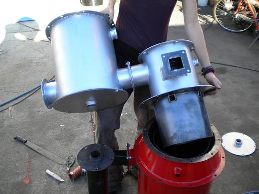
III. Pyrocoil and Drying Bucket
| Note: The DogHouse Lid is the adapting component used in the absence of the Pyrocoil to attach the Drying Bucket to the Reactor. If you do not have the Pyrocoil, continue with the steps below replacing the Pyrocoil with the DogHouse Lid. |
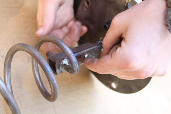
- Apply gasket and use the 5/16'' bolts to attach the Pyrocoil to the Drying Bucket.
- (Note: The 1.5 inch coupler on the Pyrocoil should be lined up in the same plane of the 1.5 inch coupler on the drying bucket for correct orientation).
- For the v3.x attach the bottom lid to the Drying Bucket. For the v4.x, leave the lid off for now, this will be attached later.
|
*For the GEK v4.x:
|
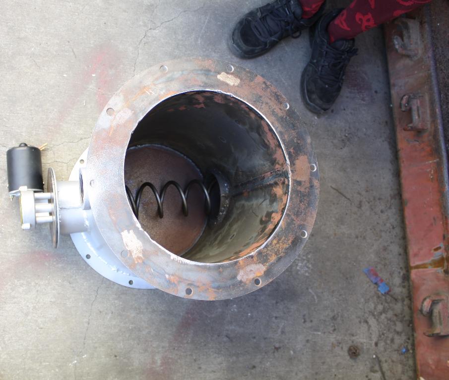
- Apply gasket to the flange of the Reactor.
- Lower the Pyrocoil into the Reactor. Align the opening at the bottom of the Drying Bucket (Gas Out Port) with the top of the Cyclone.
- Use the bolts to attach the Pyrocoil to the Reactor. Using the slotted bolt holes in the Pyrocoil, make slight adjustments to align the Gas Out Port of the Drying Bucket to the center of the Cyclone.

IV. Lighting Port
- Assemble the 7'' plumbing nipple with the 3'' nipple using a 90.
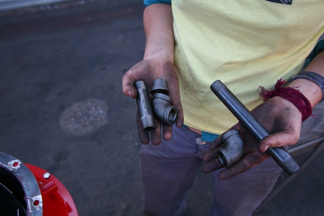

- For the Pyrocoil, do not use the second 90 at the end of the 7'' pipe nipple that is shown in the second picture above.
- Slide the Lighting Port into the 0.88 ID non-threaded port in the Pyrocoil. The Lighting Port will extend straight down to the Air Nozzles in the Reactor.
- Be sure to seal around the port with high temp mortar to prevent air leakage (make sure everything is aligned before the high temp mortar hardens permanently in 24 hours).
- When the Lighting Port is not in use, use a 1/2 inch cap at the end on the outside of the Pyrocoil.

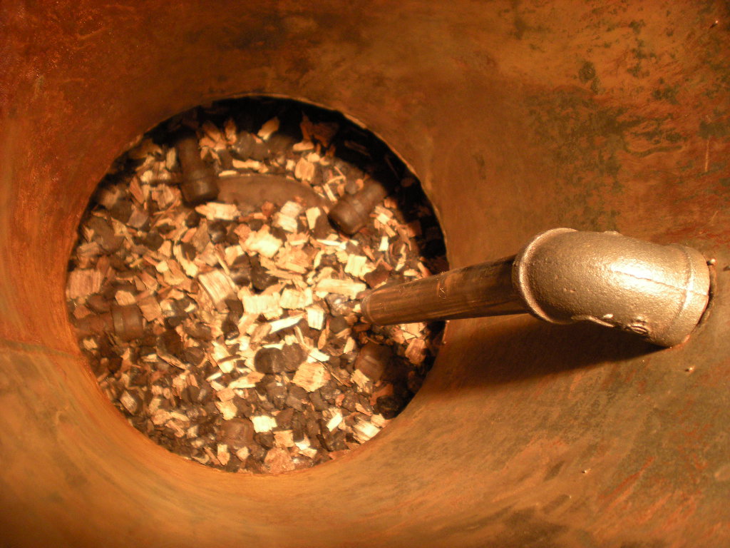
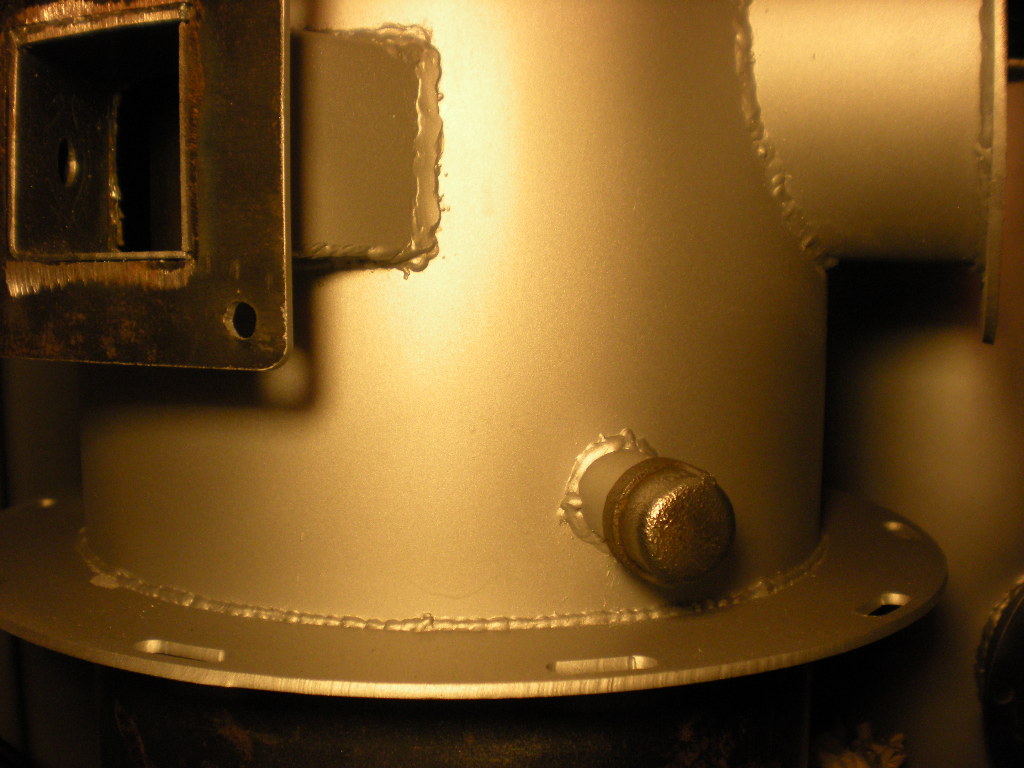
- Note: The first version of the Pyrocoil did not have a hole of the Lighting Port. If you have the ability, the tube inserted in the Pyrocoil is a 0.88 inch ID non-threaded pipe welded into the double wall.
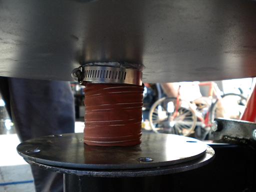
V. Gas Line Connection: Drying Bucket - Cyclone
- If needed, shorten the silicone flex line to fit between the Cyclone Tube Plate and the Drying Bucket.
- Use sealant if available around the mate, and use hose clamps to secure the connection.

|
*For the GEK v4.x:
|


VI. Fuel Level Sensor
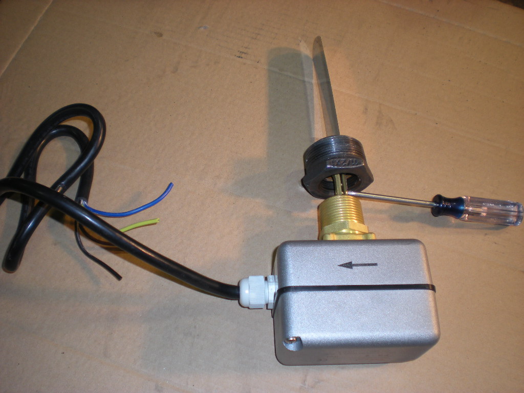
A) Paddle Switch
-
Included with the Paddle Switch, are three paddle lengths. Detach the smaller paddle on the Paddle Switch and chose the medium length paddle.
-
Align the 1''-1.5'' plumbing reducer over the Paddle Switch threads and use a philips head screw driver to attach the medium length paddle to the switching mechanism.
-
Thread on the 1''-1.5'' plumbing reducer the rest of the way.
-
Thread the Paddle Switch in to the middle bung on the Reactor Lid. Be sure that the arrow on the Paddle Switch is pointing away from the Drying Bucket.
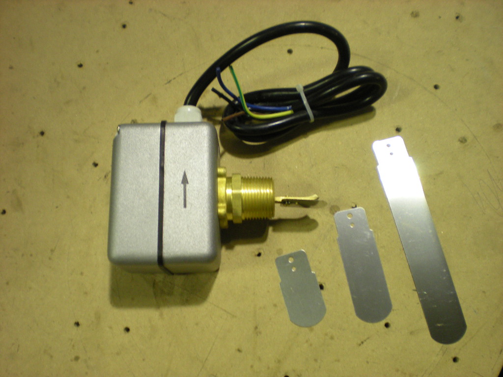
B) Wiring the Paddle Switch as the Fuel Level Sensor
- Use a 12v DC power supply or car battery to power the Auger Motor with the Paddle Switch in line to control the circuit as the Fuel Level Sensor. Connect the positive terminal of the power supply to the COM (brown, common) wire on the Paddle Switch. Connect the N.C. (black, normally closed) wire to one of the leads on the 20 Amp breaker switch. Connect the second lead on the breaker switch to the green wire on the Auger Motor. The red wire on the Auger Motor will connect to negative terminal on the power supply. This will turn the Auger Motor counter-clockwise which will cause the Auger Spiral to push the feed stock into the Reactor. (Note: Double check that the Auger Spiral is turning the correct way. If the Auger is pulling feedstock backwards into the Drying Bucket, the Auger Motor will jam and trip the breaker switch. If this happens, reverse the wire connections on the Auger Motor. Without the breaker swtich, the Auger Motor may burn out if feedstock gets jammed in the Auger).


VII. Gas Line Connection: Drying Bucket - Gas Filter
- Attach the pipe nipple to the 1.5" elbow (this is either a longer pipe or close nipple) and thread it into the bung on the Drying Bucket.
- Attach the flex tube to this Gas Out Port to the Gas Filter.
- Refer to the Basic GEK Assembly Instructions for the complete notes on this connection.

|
*For the GEK v4.x:
|

VIII. Hopper Barrel
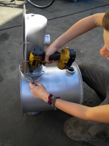
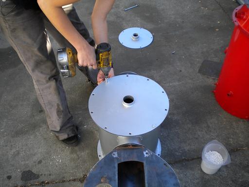
- To attach the Hopper to the Drying Bucket, add the RTV to the flange making sure the RTV also passes between the bolt holes.
- Place the silicone gasket on the flange and you may use the square monorator flange to hold the gasket in place for the RTV to set. DO NOT tighten the gasket down tight, it is too tight if you see the silicone gasket deformed and squeezing out from between the flanges.
- Take the square monorator flange off after the RTV has somewhat set, this will make it easier to maintain a good seal when then attaching the hopper barrel.
- The Hopper Barrel will attach to the Drying Bucket in the same manner that it would attach to the Reactor for the Basic GEK.
- Refer to the Basic GEK Assembly Instructions for the Hopper Barrel assembly step: http://wiki.gekgasifier.com/w/page/27905807/Assembly%20Instructions%20for%20the%20GEK%20v4%20Kit


|
*For GEK v4.x:
|
Now you are done! You have graduated to the next level. Proceed to the Operating Instructions: http://wiki.gekgasifier.com/w/page/6123713/First-Run%20Start-Up%20Instructuions%20for%20GEK%20v30

return to How to Build and Run the GEK Gasifier